Home › Unlabelled ›
What Are Circuit Diagrams / | Repair Guides | Wiring Diagrams | Wiring Diagrams ... / Electric circuit, network, complex circuits and other types of circuits.
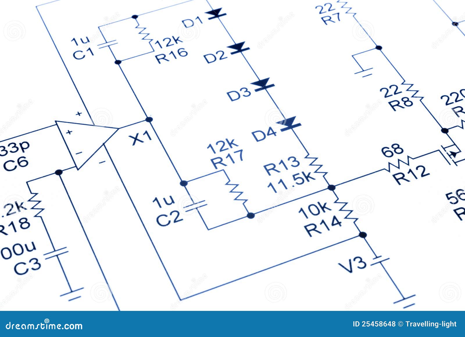
What Are Circuit Diagrams / | Repair Guides | Wiring Diagrams | Wiring Diagrams ... / Electric circuit, network, complex circuits and other types of circuits.. They serve as a map or plan for assembling electronics projects, and they are easy to read — far easier than understanding how the circuits they describe actually work. These two different types of circuit diagrams are called pictorial (using basic images) or schematic style (using. Before talking about a circuit diagram, let us recall circuits. Schematics, circuit diagrams, wiring diagrams, electrical diagrams are commonly used in engineering diagrams. This circuit reference designator normally consists of one or two letters followed by a number.
Actual to arrange blob capacitance circuit diagram controls to draw drawing. What happens if a short circuit takes place in an electric circuit? It shows the flow and relationships between components in an electrical circuit. Schematics, circuit diagrams, wiring diagrams, electrical diagrams are commonly used in engineering diagrams. They serve as a map or plan for assembling electronics projects, and they are easy to read — far easier than understanding how the circuits they describe actually work.
An HVAC tech confirmed that the blower motor failed in my ... from f01.justanswer.com Circuit symbols and circuit diagrams. All circuit symbols are in standard format and can be used for drawing schematic circuit diagram and layout. Electrical circuits and how to draw them, circuit symbols, introduction to series and parallel circuits. Actual to arrange blob capacitance circuit diagram controls to draw drawing. What is an electrical network? A final means of describing an electric circuit is by use of conventional circuit symbols to provide a schematic diagram of the circuit and its components. Circuit diagrams can be created with thousands of possible shapes and icons and lucidchart's. What are the basic components of any electric circuit?
In order to learn how to read a circuit diagram, it is necessary to learn what the schematic symbol of a component looks like.
Circuit symbols and circuit diagrams. Circuit diagrams can be created with thousands of possible shapes and icons and lucidchart's. Electric circuit, network, complex circuits and other types of circuits. Electrical circuits and how to draw them, circuit symbols, introduction to series and parallel circuits. A circuit diagram is a graphical representation of an electrical circuit. When developing a circuit diagram or schematic, it is necessary to identify the individual components. A circuit diagram is termed as: The series resonant circuits on the circuit diagram represent the torsional resonators, and the shunt capacitors represent the coupling wires. Always try to make the wires straight lines. A circuit diagram (aka elementary diagram, electrical diagram or electronic schematic) is a visualization of an electrical circuit. Design circuits online in your browser or using the desktop application. Schematics, circuit diagrams, wiring diagrams, electrical diagrams are commonly used in engineering diagrams. Circuit diagrams are visual representations of electrical circuits, using lines and symbols.
This can only be shown by bridging them or by drawing them without blobs. A circuit diagram, or schematic, is a picture of how the components in a circuit are connected together. Circuit diagrams are a pictorial way of showing circuits. Electricians and engineers draw circuit diagrams to help them design the actual circuits. The series resonant circuits on the circuit diagram represent the torsional resonators, and the shunt capacitors represent the coupling wires.
Electronic Circuit Diagram Audio Royalty Free Stock Photos ... from thumbs.dreamstime.com What is a circuit diagram? From transistors to logic gates, you'll find icons that are. Circuit diagrams are used for design, construction and maintenance of the electrical and electronic equipment. A drawing meant to depict the physical arrangement of the wires and the components they connect is called artwork or layout, physical design, or wiring diagram. Explore the different components of a circuit diagram and their symbols. Always try to make the wires straight lines. Our circuit diagram symbol library is schematic and includes many icons commonly used by engineers. All circuit symbols are in standard format and can be used for drawing schematic circuit diagram and layout.
When circuits are drawn some wires may not touch others.
Symbol usage depends on the audience viewing the diagram. Circuit diagrams can be created with thousands of possible shapes and icons and lucidchart's. Circuit diagrams are used for design, construction and maintenance of the electrical and electronic equipment. What happens if a short circuit takes place in an electric circuit? When developing a circuit diagram or schematic, it is necessary to identify the individual components. Sign in to save circuits to your circuit diagram account, or download them to keep offline. Always try to make the wires straight lines. They serve as a map or plan for assembling electronics projects, and they are easy to read — far easier than understanding how the circuits they describe actually work. A drawing meant to depict the physical arrangement of the wires and the components they connect is called artwork or layout, physical design, or wiring diagram. These are used for designing, constructing and troubleshooting in an electronic circuitry. Though it is not standardised, the schematic diagrams are organised on a page from left to right and top to bottom. A circuit diagram is a visual display of an electrical circuit using either basic images of parts or industry standard symbols. Electric circuits like ac lighting circuit, battery charging circuit, energy meter, switch circuit, air conditioning circuit, thermocouple circuit, dc lighting circuit, multimeter circuit, current transformer circuit, single phase motor circuit are explained with diagrams.
A circuit diagram is a graphical representation of an electrical circuit. Circuit diagrams are used for design, construction and maintenance of the electrical and electronic equipment. An electric circuit includes a device that gives energy to the charged particles constituting the current, such as a battery or a generator; Electrical circuits and how to draw them, circuit symbols, introduction to series and parallel circuits. A drawing meant to depict the physical arrangement of the wires and the components they connect is called artwork or layout, physical design, or wiring diagram.
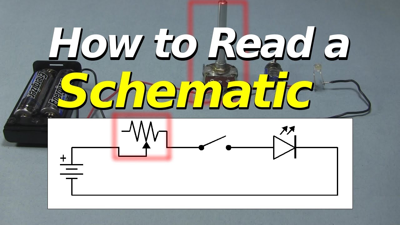
How to Read a Schematic - YouTube from i.ytimg.com We use circuit symbols to draw diagrams of electrical circuits, with straight lines to show the wires. The series resonant circuits on the circuit diagram represent the torsional resonators, and the shunt capacitors represent the coupling wires. They serve as a map or plan for assembling electronics projects, and they are easy to read — far easier than understanding how the circuits they describe actually work. Circuit diagrams are visual representations of electrical circuits, using lines and symbols. A visual display of an electric circuit using either industry standard symbols or basic images of parts. Circuit diagrams show the connections as clearly as possible with all wires drawn neatly as straight lines. A circuit diagram would display the inputs according to their sign with respect to the output when a particular input is greater than the other. A drawing meant to depict the physical arrangement of the wires and the components they connect is called artwork or layout, physical design, or wiring diagram.
This can only be shown by bridging them or by drawing them without blobs.
They serve as a map or plan for assembling electronics projects, and they are easy to read — far easier than understanding how the circuits they describe actually work. The series resonant circuits on the circuit diagram represent the torsional resonators, and the shunt capacitors represent the coupling wires. A circuit diagram, or a schematic diagram, is a technical drawing of how to connect electronic components to get a certain function. Circuit diagrams are a pictorial way of showing circuits. But, if you are a beginner and you don't know what an ldr is, what a transistor is or what a voltage divider is, then you won't have the foundation to understand the. Design circuits online in your browser or using the desktop application. Which one is used depends on the intended audience. You may have heard them an electronic schematic to electronics is what a recipe is to a chef. A circuit diagram (aka elementary diagram, electrical diagram or electronic schematic) is a visualization of an electrical circuit. Circuit diagrams are used for design, construction and maintenance of the electrical and electronic equipment. In order to learn how to read a circuit diagram, it is necessary to learn what the schematic symbol of a component looks like. A circuit diagram, or schematic, is a picture of how the components in a circuit are connected together. Electricians and engineers draw circuit diagrams to help them design the actual circuits.