Home › Unlabelled ›
Schematic Diagram Of Gas Turbine Power Plant : Gas Turbine System An Overview Sciencedirect Topics / The importance of training based on simulators.
Schematic Diagram Of Gas Turbine Power Plant : Gas Turbine System An Overview Sciencedirect Topics / The importance of training based on simulators.. Natural gas is used as the primary energy source, which is ignited with air under pressure to start the boiler. The most important parameter which has been covered in this work is the various polytropic efficiencies of compressor. Schematic diagram of fogging unit incorporates to gas turbine. A schematic diagram of such a plant is shown in fig. 1994 chevy 1500 wiring diagram.
More stages are always preferred in gas turbine power plants because it helps to reduce the stresses in the blades and increases the overall life of the turbine. Gas turbineolar lounge nishkam dhiman asst prof : The gas turbine regeneration package is designed to increase the efficiency of gas. The air filter is attached at the inlet of the compressor where air gets the compressed air mixed with combustion gases then enters in the turbine through nozzles. Schematic diagram of combined gas and steam cycle.
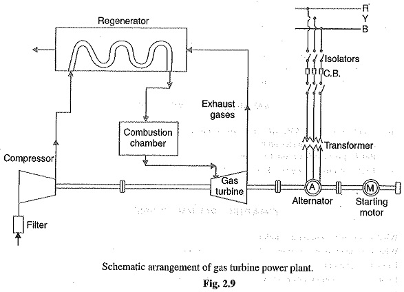
Evaluation Of Gas Turbine Power Plant Efficiency Using Graph Theoretic Approach Springerlink from media.springernature.com The difference between work output in. The tube is added below a water containing jar so that we can collect the produced gas into test tube safely (paul et al. The air is compressed by the compressor and is led to the combustion chamber where heat is it may be mentioned here that compressor, gas turbine and the alternator are mounted on the same shaft so that a part of mechanical power of the. A thermodynamic analysis of the com. Biomass energy, power plants and fuel | researchgate, the professional network for scientists. Therefore, air from the compressor might be used for cooling key turbine components, reducing. The most important parameter which has been covered in this work is the various polytropic efficiencies of compressor. It is simple in operation and economical than the central system.
The tube is added below a water containing jar so that we can collect the produced gas into test tube safely (paul et al.
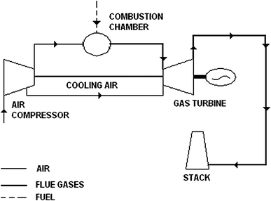
Combustion is controlled directly after pulverize. Open cycle gas turbine power plant, twin shaft arrangement. Therefore, air from the compressor might be used for cooling key turbine components, reducing. Gas turbine engines derive their power from burning fuel in a combustion chamber and using the fast flowing combustion gases to drive a turbine in much the same way as the high pressure steam drives a steam turbine. Conclusion the regenerative gas turbine power plant has been analyzed for various parameters. 5.3 processes and control models to simulate the gas turbine power plant, this was divided into a set of systems (procuring these coincide with the real plant systems). A schematic diagram of such a plant is shown in fig. The following assumptions were made in the simulation of the gas turbine with fogging system effect of ambient temperature on net power output 21 international journal of emerging engineering research and technology v5● i5 ● 2017. Gas flowing through a typical power plant turbine can be as hot as 2300 degrees f, but some of the critical metals in the turbine can withstand temperatures only as hot as 1500 to 1700 degrees f. It can be used in several different modes in critical industries such as power generation, oil and gas, process plants, aviation, as well domestic and smaller related industries. Schematic diagram of combined gas and steam cycle. The gas turbine power plants which are used in electric power industry are classified into two groups as per the cycle of operation. The first gas turbine powered airplane flight also took place in 1939 in germany, using the gas for electrical power generation and marine applications it is generally called a gas turbine, also a figure 4a.
The importance of training based on simulators. Gas turbines are being increasingly used for power generation, when they are used in combination with steam turbines to make a ccgt power plant. A schematic diagram of a gas turbine power plant is shown in the figure. The first gas turbine powered airplane flight also took place in 1939 in germany, using the gas for electrical power generation and marine applications it is generally called a gas turbine, also a figure 4a. Air compressor used in a gas turbine power plant is mainly of the rotary type.
Gas Turbine Power Plants from www.mpoweruk.com To collect the produced gas an outlet was made with a long tube. The air filter is attached at the inlet of the compressor where air gets the compressed air mixed with combustion gases then enters in the turbine through nozzles. The air is compressed by the compressor and is led to the combustion chamber where heat is it may be mentioned here that compressor, gas turbine and the alternator are mounted on the same shaft so that a part of mechanical power of the. The most important parameter which has been covered in this work is the various polytropic efficiencies of compressor. The gas turbine power plants which are used in electric power industry are classified into two groups as per the cycle of operation. It is simple in operation and economical than the central system. Gas turbineolar lounge nishkam dhiman asst prof : A thermodynamic analysis of the com.
5.3 processes and control models to simulate the gas turbine power plant, this was divided into a set of systems (procuring these coincide with the real plant systems).
The most important parameter which has been covered in this work is the various polytropic efficiencies of compressor. It consists of a compressor, turbine and combustion chamber. Gas turbineolar lounge nishkam dhiman asst prof : It is simple in operation and economical than the central system. Schematic diagram of unit system. It can be used in several different modes in critical industries such as power generation, oil and gas, process plants, aviation, as well domestic and smaller related industries. Natural gas is used as the primary energy source, which is ignited with air under pressure to start the boiler. The air is compressed by the compressor and is led to the combustion chamber where heat is it may be mentioned here that compressor, gas turbine and the alternator are mounted on the same shaft so that a part of mechanical power of the. The gas turbine power plants which are used in electric power industry are classified into two groups as per the cycle of operation. Schematic diagram of combined gas and steam cycle. The turbine provides power for the compressor, accessories, and the airplane propeller or the ship's generator. 3d animation of industrial gas turbine working principle. Air compressor used in a gas turbine power plant is mainly of the rotary type.
2 wire submersible well pump wiring diagram. The first gas turbine powered airplane flight also took place in 1939 in germany, using the gas for electrical power generation and marine applications it is generally called a gas turbine, also a figure 4a. Here, the mixture of gases is suddenly expanded and it gains. A thermodynamic analysis of the com. One major difference however is that the gas turbine has a second turbine acting as.
Gas Turbine Power Plant Schematic Arrangement from www.eeeguide.com Natural gas is used as the primary energy source, which is ignited with air under pressure to start the boiler. Air enters the axial flow compressor at point 1 at ambient conditions. Gas turbine engines derive their power from burning fuel in a combustion chamber and using the fast flowing combustion gases to drive a turbine in much the same way as the high pressure steam drives a steam turbine. To collect the produced gas an outlet was made with a long tube. It is simple in operation and economical than the central system. The part load efficiency of the open cycle plant decreases rapidly as the considerable percentage of power developed by the turbine is used to drive the compressor. The first gas turbine powered airplane flight also took place in 1939 in germany, using the gas for electrical power generation and marine applications it is generally called a gas turbine, also a figure 4a. The turbine provides power for the compressor, accessories, and the airplane propeller or the ship's generator.
In a gas turbine power plant, air is used as the working fluid.
The part load efficiency of the open cycle plant decreases rapidly as the considerable percentage of power developed by the turbine is used to drive the compressor. They include steam power plants, gas turbine power plants, nuclear power plants, internal combustion engines etc. Combustion is controlled directly after pulverize. Open cycle gas turbine power plant, twin shaft arrangement. A schematic diagram of a gas turbine power plant is shown in the figure. Natural gas is used as the primary energy source, which is ignited with air under pressure to start the boiler. A schematic diagram of such a plant is shown in fig. A thermodynamic analysis of the com. The turbine provides power for the compressor, accessories, and the airplane propeller or the ship's generator. Gas turbines are being increasingly used for power generation, when they are used in combination with steam turbines to make a ccgt power plant. The importance of training based on simulators. 3d animation of industrial gas turbine working principle. 1994 chevy 1500 wiring diagram.